Displacement &Semi-Displacement
(or Semi-Planing)
Boat Calculations (English Units)
Description:
This popular boilerplate template performs powering
calculations (power prediction methods) applicable to two modes of boat or
ship operation. The first is the displacement mode and the second
involves semidisplacement or semiplaning mode of operation. Result graphs are
automatically generated and show speed in knots versus the brake horsepower required. Because the input weight is important, this
spreadsheet is setup to conveniently calculate the vessel's weight in various
operational conditions. This template also checks to see if the
vessel will go it's intended range, if the installed horsepower is
adequate and if the stern's quarter butt exit angle permits the input
speed.
These calculations apply generally to calm water performance.
The first set of calculations are for most types displacement and
semi-displacement, or semi-planing vessels. They
are based on procedures described by Dave Gerr in Reference D. The
second set of calculations applies only to displacement vessels (that are
optimized for displacement length ratio and prismatic coefficient) and are
adapted from methods presented by Robert Beebe in Reference K. References D and K are
recommended reading for understanding the processes automated in this
spreadsheet. The other references contain supplemental information,
but they are not needed for implementation of these calculations. This template is
designed for use with English units.
The first set of output computations apply to displacement and
semi-displacement vessels. Semi-displacement, or semi-planing, boats
normally operate at speed length ratios, V /
LWL1/2, from about 1.3 to 1.4 all the way up to about three. However, in order
to reach speeds in excess of maximum displacement speed, a vessel must
have the appropriate aft quarter butt exit angle. An example drawing of
this exit angle is provided in the spreadsheet along within the output calculations. If the
aft quarter butt exit angle is too large, these calculations are
automatically modified to only go up to the maximum speed that is
allowable for the exit angle that is present. However, the automated
result will never be less than the maximum allowable displacement speed.
Since all this automated, a complete understanding is not crucial. What
must be understood is decreasing the hull exit angle will often let the
spreadsheet evaluate higher speeds.
The second set output of calculations apply only to
displacement mode. Displacement ships can only go up to their
maximum displacement speed which is calculated in this spreadsheet.
This maximum displacement speed is a function of both the weight and the
length of the boat. The maximum speed length ratio normally
associated with displacement mode is usually between 1.3 and 1.4.
But light and long vessels can exceed this displacement limit and these
effects are taken into consideration by this spreadsheet.
This second set of calculations assume that the boat has been designed
with an optimum prismatic coefficient, that corresponds to it's
displacement length ratio. Beebe discusses these optimization
techniques in References G and K. Other references also discuss the
technique.
There are several advantages and benefits
associated with these calculative methods. First this approach saves
time. Numerous computations are automatically and quickly done on
your input data. This approach is also cost effective because the
calculations are already setup for you. As a result your research
time is minimized to familiarization of concepts when necessary and not in
time consuming procedural development activities.
Electronic
Document Type: Microsoft Excel
spreadsheet Cost:
$25 US funds
Number of
Pages: Inputs Sheet, Outputs Sheet,
References, Figure and Notes Sheet, F2 Function SLR Page, Use Terms Page and Instructions
Page.
Inputs:
 |
Hull characteristics
 |
Length Over All, LOA, feet (optional input) |
 |
Length of Waterline, LWL, feet |
 |
Beam on Waterline, BWL, feet (optional input) |
 |
Exit Angle,
qAFT,
of Aft Quarter Butt, an explanatory diagram is provided on the
References Sheet of this
template. This value is critical for proper hull operation and it is
therefore checked in this analysis. For complet details about this
requirement refer to Pages 12 and 13 of Reference D.
|
|
 |
Weight information
 |
Vessel light ship weight, pounds, the
weight without any
people, luggage, personal gear, provisions, stores, fluids or cargo on
board |
 |
Weight margin on light ship, percent. This
is optional input and default values are provided. |
 |
Cargo weight, pounds, usually can be left at zero default
value. Examples of cargo weight are fuel drums on deck, weight of
fish and ice on board. |
 |
Number of crew and number of passengers,
integer |
 |
Additional equipment not included in light ship,
pounds |
 |
Duration of voyage, days, for calculating
provisions and stores, this value can often be left at it's default
value which is equal to zero |
 |
Personal crew gear and passenger luggage,
pounds, can be set to zero |
 |
Portions of total fluid capacities to be
applied in analysis, default values that are set at 2/3 are provided,
however these values may be specified as inputs. |
 |
Main propulsion fuel tank capacity, gallons,
&
fuel type (diesel or gasoline). This is a highly recommended input
value, if provided an estimate of the vessel's range will be automatically
computed by this spreadsheet. |
 |
Potable water tank capacity, gallons |
 |
Sewage holding tank capacity, gallons |
|
 |
Propulsion Plant Details:
 |
Installed brake horsepower,
if unknown guess an amount, this value can be easily changed once these
calculations are done. |
 |
Parasitic loads, horsepower, for pumps,
generators, etc. |
 |
Continuous operating rpm, percentage
of maximum, guideline values are
given on the input sheet, simply select the
applicable rpm percentage |
 |
Shafting efficiency, ratio, guideline values
are given, select appropriate value |
 |
Propeller efficiency, ratio, a default value is
present, however another value may be substituted in the calculations |
 |
Vessel range required, nautical miles, optional
input. If this value is specified this spreadsheet will
automatically determine if the tanks provided are adequate to make the
voyage distance specified by this input. |
|
Outputs:
 |
For each of the input speeds the following is
output are computed by this template:
 |
Effective Horse Power,
EHP |
 |
Brake Horse Power,
BHP |
 |
Continuous Horsepower,
BHP0 |
 |
Estimated Range, nautical miles,
from fuel consumption rate and tank capacity |
|
 |
The total operational weight is automatically
computed based on light ship margin selected, cargo present, persons
aboard, voyage duration which affects stores and provisions, selected
operational tank capacities and gear on board. |
 |
Supplemental values like displacement
length ratio, estimated maximum possible displacement speed, estimated
fuel consumption rate, speed length ratios. |
 |
Calculative Checks are made for the
following criteria:
 |
Check if installed horsepower will meet the required horsepower
needed for continuously operating at the speed computed. It is
important to know that If the speed involved is not a continuous
operating speed this check should be ignored. These speeds include
those used for burst mode operation (operations only for short periods at this speed) and transitory
speeds (when accelerating or decelerating towards a continuous operating
speed). |
 |
Check if range requirements will be meet at the speed evaluated.
If this check is met the fuel tanks are adequately sized, if not the
fuel tanks should be increased in size, but only for continuous
operating speeds. |
 |
Check if hull bottom aft exit angle
at quarter butt is appropriate for speed computed. If this check
is not met the bottom shape at the aft end of the hull should be
flattened more so this speed can be reached by the hull. |
|
Recommended
Reading:
 |
Reference D: Dave Gerr, Propeller Handbook,
International Marine, 1989, Camden, Maine. |
 |
Reference E: Dave Gerr, Nature of Boats,
International Marine, 1995, Camden, Maine. |
 |
Reference F: John Teale, article
entitled "Teale on Trawlers," Motor Boating and Sailing, June
1981 issue. |
 |
Reference G: Robert P. Beebe, article
entitled "Trawlers - Designing by the Numbers," Motor Boating and
Sailing, January 1977 issue. |
 |
Reference H: Alfred D. Isaacson,
paper entitled "Sewage Polution Control: A Guide for the Ship Owner &
Design," SNAME Marine Technology, July 1977 issue.. |
 |
Reference I: S9086-C6-STM-010/CH-096R1 "Naval Ships'
Technical Manual Chapter 096 Weights & Stability," NAVSEA, 2 August
1996. |
 |
Reference J: Detroit Allison Diesel,
article entitled "Calculating Hull Speed," Motor Boating and
Sailing, February 1978 issue. |
 |
Reference K: Robert P. Beebe and
James F. Leishman, Voyaging Under Power, Third Edition,
International Marine, 1994, Camden, Maine. |
Terms:
Prior to purchase, read our End
User License Terms.
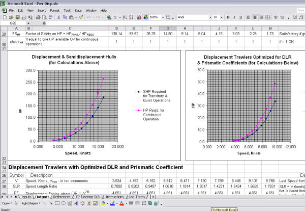
Download
Now: click the following hyperlink to pay
$25 fee and then immediately download the zip file containing the template.
Minimum
System Requirements: Windows 95/98/NT/2000/XP
Sample:
A sample of an output page is shown below.
|

|