|
For marine design,
composite beam analysis is applied when two or more materials are present
within a beam's cross section. Among other things, stiffness
differences (materials with differing Young's Modulus values) results in a
shift in the location of the cross section's neutral axis.
Discussion in this article is generally confined to a two material cross
section. But in principle, this equivalent area method can be
expanded to accommodate more than two materials.
This type of
analysis is required quite often for ship and boat design. For
example, in boat hull framing design, you may have a fiberglass hat
frame with a layer of carbon fiber on the top surface. In ship
design, you may have a steel hull and an aluminum deckhouse. This
method can also be used by civil engineers who are evaluating stresses
in steel reinforced concrete beams. There are many other scenarios
possible.
The "equivalent
area method" is easy to learn, simple to implement, fairly accurate and
is adequate for cases involving boat, yacht, ship and barge structural
cross sections. A more direct method or a finite element method
can be used if more a sophisticated or more accurate model is required.
With the
"equivalent area method" one of the materials is selected to be the base
material. The base material is usually the most dominant material
present within the cross section. The area of the other material
is then adjusted laterally to emulate the base material's elastic
characteristics. The height of all materials present must
never be modified with this method. In other words, area
transformations for equivalent properties must always be lateral or else
this method will not work.
Some other
limitations also apply to this method. This method will work only
if the elastic limit, in any of the materials present, is not exceeded.
So, if all working stresses, in all materials, are below their yield
strengths, then this method should work fine. Also differing
materials must be adequately connected to each other, so that shearing
will not occur at the interfaces. For instance, aluminum
superstructures must be securely bolted or data-clad welded to their
steel hulls, and these superstructures must run a substantial length of
the hull in order to be effective. The composite member can also
be limited by allowable strains of the resin or the laminate.
Bear in mind when
doing composite section analysis, that items closer to the neutral axis
can actually experience higher stress than those that are further away.
For example a mahogany beam sitting on top of a steel beam. The
steel beam under the mahogany beam would likely be under higher stress
than the mahogany. For this reason, one should proceed more
carefully than one would with isotropic material sections.
Consideration should be given to stresses levels throughout the entire
height of a composite beam's cross section. If the equivalent area
calculations are made with a spreadsheet, this checking process can be
quick and relatively easy.
Theoretical Derivation of Formulas
Theoretical derivations are straight forward. For the cross section of the
second material present (which is identified as 2), the object is to
obtain an equivalent section of base material (which is identified
as 1).
For equivalence
the strain in both the original and transformed members must be
the same for a given loading.
For the base material the strain is Strain1 = Stress1 /
E1 and
for the second material the strain is Strain2 =
Stress2 / E2
Equivalence requires that Strain1 = Strain2,
therefore Stress1 / E1 = Stress2 / E2; or rearranging we obtain:
Stress2 / Stress1 = E2 / E1
Formula 1
Also for equivalence, the force carried by the transformed
section must equal
the force that is carried by the original second material section.
For the base material the force is Force1 = Stress1 x A1
and
for the second material the force is Force2 =
Stress2 x A2
Since
equivalence requires that Force1 = Force2,
therefore Stress1 x A1 = Stress2 x A2; solving obtain
A1 = (Stress2/Stress1) x A2 and rearranging obtain
Stress2 / Stress1 = A1 / A2 Formula 2
Combining the strain (Formula 1) and force (Formula 2) requirements and rearranging
obtain the following formulas for equivalent area:
A1 = (E2 / E1) x A2
Formula 3
or A1 = N2 x A2,
Formula 4
where N2 = E2 / E1
Formula 5 N2 is called
the Transformation
Factor or Moduli Ratio
Therefore, the equivalent area of base material is equal to the second materials area
multiplied by the transformation factor (or moduli ratio which is the
second material's modulus divided by the base material's modulus).
Since the height must remain the same for this method to work, the
original width of the second material is multiplied by the moduli ratio
to obtain an new equivalent width of base material. So before the
transformation the second materials height is h and it's width is w.
After the transformation the second materials height remains at h, and
the it's new equivalent width is now N2 x w or (E2/E1) x w.
A formula is now derived to convert the equivalent base material stress (Stess1)
calculated in the equivalent section to the actual stress (Stress2)
present in the second material's actual section. This formula is
obtained by rearranging Formula 1. The result is then combined
with Formula 5 to incorporate the transformation factor.
Stress2
= Stress1 x (E2 / E1)
Formula 6
Stress2 = Stress1 x N2
Formula 7
Several sources use Formula 7. In other words these sources calculate the
equivalent section stress in the base material first and then multiply
it by the transformation factor.
When working with spreadsheets there is another more convenient way to get the stress
level in Material 2. This spreadsheet method takes the section
modulus of the transformed section and divides it by the transformation
factor. This method skips having to first calculate the stress in
the equivalent base material. This method is derived as follows:
Stress1 = M / SM1, for the equivalent section of base material
Formula 8
Stress2 = M / SM2, for the original second material
Formula 9
The applied moment is the same for both the equivalent material and
second material sections,
so have M = M in Formulas 8 and 9, rearranging obtain:
Stress2 x SM2 = Stress1 x SM1
Rearranging we obtain Stress2 / Stress 1 = SM1 / SM2
Combine the preceding formula with Stress2 / Stress 1 = N2
(rearranged Formula 7)
which is then arranged to give the following formula relating
section modulus values:
SM2 = SM1 / N2
Formula 10
Rewritten, by combining Formula 10 and Formula 5, and
rearranging obtain:
SM2 = SM1 (E1 / E2)
Formula 10a
Combining Formula 9 and Formula 10 have the following:
Stress2 = N2 x M / SM1 Formula 11
So the equivalent area section modulus (SM1 of the base material) can be divided
by the transformation factor (N2) to obtain the section modulus
(SM2) applicable to the original section of second material
involved (as per Formula 10).
Applicability Note 1: Before proceeding any
further, some clarification is required. The above
Formulas 10 and 11 apply to the same point in a cross section.
In these formulas the number 1 represents this point in the
transformed cross section consisting of Material 1 and the
number 2 represents this same point but this time in Material 2
with a non-transformed (or original) cross section. This
is an important distinction, because the next two formulas,
though they can apply to a single point as just mentioned, they
are usually applied to completely different points within the
cross section.
Substituting SM = I /y into above is Formula 11 and is rewritten
as Formula 12 as follows:.
Stress2 = N2 x M x (y2 / I)
Formula 12
Since stress = M / (I / y) by definition, the stress present in Material 1 is:
Stress1 = M x (y1 / I)
Formula 13
Formulas 12 and 13 are very important and are commonly presented in
composite analysis references. In these formulas, I is the
transformed moment of inertia of the cross section. Note
that the same I value is used for both materials present.
However, the y values do change dependant on the material
location in the cross section. For formula 12, the term y2
represents the maximum distance from the neutral axis to the
furthest portion of Material 2 in the cross section. For
formula 13, the term y1 represents the maximum distance from the
neutral axis to the furthest portion of Material 1 in the cross
section.
All the preceding commentary applies to calculating the "available" section modulus.
This available section modulus is the result of materials present and
the shape of the cross section. Though not usually explicitly
calculated, a "required" section modulus can be determined through First
Principle Analysis. Normal inputs for required section modulus
values are loadings, the geometry present, and allowable stresses.
An applied moment is usually generated and utilized for First Principles
Analysis. Though one is inferred (or implied), a "required"
section modulus is not normally calculated. What usually happens
is the applied moment is divided by the "available" section modulus to
determine the stresses present. The allowable stresses are then
divided by the stresses present to give the factor of safety present.
If the value is less that one the structure is considered inadequate.
FS1 = Stress1a / Stress1
Formula 14
FS2 = Stress2a / Stress2
Formula 15
Besides first
principles, the marine industry also often has another "required"
section modulus. This "required" section modulus computed through
application of classification society rules. Reference 5 is an
example of these types of rules. These rules have similar inputs
to first principles and they also involve loadings, span, allowable
material stresses and often other factors to determine a required
section modulus. In Part 4.4.5b of Reference 5, American Bureau of
Shipping, the classification society in this case, requires that the
required section modulus for the second material be modified as follows
(the letter "r" prior to the material numerals indicates "required"
section modulus. The letter "a" after material numerals refers to
"allowable" stresses):
SMr2
= SMr1 x (Stress1a / Stress2a)
Formula 16
Where Stress2a ("u" in the lingo of reference 7) is the verified flexural strength of
the alternate laminate and where Stress1a is the verified strength of
the basic laminate. But when Stress1a and Stress2a are not be
readily available, it can theoretically be proven that substituting E1
for Stress1 and E2 for Stress2 is equivalent. The proof goes as
follows: Formula 1 can theoretically be modified by inserting the
verified (or allowable) flexural stresses instead of the stress levels
that are present. The result is:
(Stress2a / Stress1a) = E2 / E1
Formula 17
Formulas 16 is
rearranged and then combined with Formula17, the combined result is then
rearranged to yield the following:
SMr2
= SMr1 x (E1 / E2)
Formula 18
This formula is very similar to Formula 10a. The second material modifications for
section modulus "available" and section modulus "required" is almost
identical. This is as it should be.
Note: The classification society may or may not allow the preceding substitution.
At any rate a documented allowable stress should be available to the
designer to verify that the laminate is not overstressed during first
principles analysis. If acceptable stress levels are proven, then
the classification society will more likely accept the substitution of
Formula 16 with Formula 18 above.
For composite marine design, Reference 7 has material properties listed for a large
number of modern laminates. References 5 and 8 also has some
material properties listed within them.
Cautionary note is added on Page 4, Enclosure A of
References 6 and on Page 173 of Reference 7; they state the following:
"Reinforcing fibers of different strengths and different moduli can be
limited in the amount of strength that the fibers can develop by
the maximum elongation tolerated by the resin and the strain to
failure of the surrounding laminate. Therefore, the
strength of the overall laminate should be analyzed, and for
marginal safety factor designs or arrangements meeting the
minimum of a rule, tests of a sample laminate should be
conducted to prove the integrity of the design."
The considerations of this cautionary note are beyond the scope of
this short article. For details and for doing analysis
regarding this matter, recommend starting with Reference 7.
Calculative procedure notes: This article is based on
the calculative procedures contained in References 1 through 7.
However, Reference 6 (Enclosure A, Page 4) and Reference 7 (Page
173) modify the required section modulus by also multiplying it
by the ratio of material ultimate strengths. Reference 5
and this article (based on the derivations above) do not
incorporate this modification to the required section modulus.
As just shown, the beauty of this method, is that the moment of inertia of the
"transformed" section can be calculated simply as a single material.
Also, the transformation of materials is easy, in that the width
of each non-base material element is simply multiplied by an appropriate
transformation factor to get the transformed width for that element.
Additionally, once this transformed moment of inertia is calculated, it
is used for all the materials present. All that needs to be done
for an "available" section modulus calculation, is to divide this
transformed moment of inertia by the y value for the point under
consideration, and if its not the base material divide it by the
appropriate transformation factor. Also if a "required" section
modulus is calculated from other sources, all that needs to be done is
have it divided by the transformation factor, if it is not of the base
material. For the base of material, the transformation factor is
not used.
For an illustration of application with respect to this theoretical derivation,
refer to the article entitled "Example
of Composite (Laminated) Section Analysis, Equivalent Area Method."
Application of Theory,
Characteristics that Apply to Examples that Follow
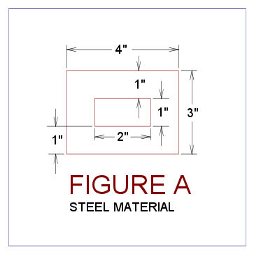
The original (or second) material cross section is for Example One and Two is a steel
rectangular tube with 3" overall height with a 4" overall width and a
wall thickness of 1" thick. This means that the tubes interior
dimensions is are 1" high x 2" wide.
Three examples follow. The following material characteristics applies to all the
examples.
Material1, the base material is Aluminum, with E1 = 10 million psi.
Material2, the original (or second) material is Steel, with E2 = 30 million psi.
The Transformation Factor (or Moduli Ratio) is calculated as follows:
N2 = E2 / E1 = 3.00
Example One - Converting a Second Material Element into an Equivalent
Area of Base Material Element
An original steel
member (or second material cross section) is shown in Figure A.
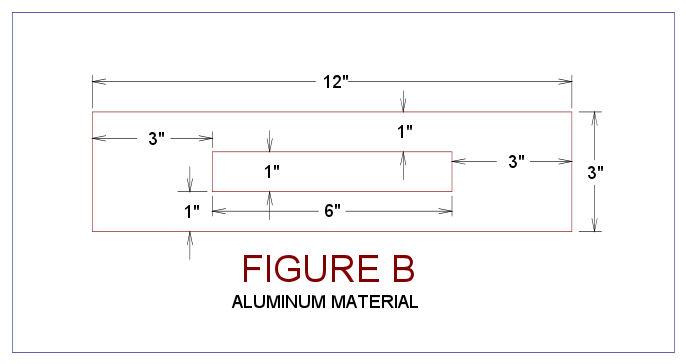
Converting this original steel cross section to a equivalent aluminum cross section is
accomplished as follows:
The interior width
of 2" is multiplied by N2 to obtain 6". The exterior width is the
shell thickness of 1" is multiplied by N2 to obtain 3". No heights
have changed. So the equivalent area overall cross section width
is 6" + 3" x 2 = 12". The height of the upper and lower
interior walls remains the same at 1" thick, but the width of the
exterior walls are now 3" on each side. The overall height of 3"
remains the same. This equivalent aluminum section is shown in
Figure B below:
The equivalent moment of inertia for this equivalent area section is computed as follows:
I = 2 x [(1")2
x (1"x 6") + (1/12) x 6" x 1"3] + 2 x [(0")2
x (3"x 3") + (1/12) x 3" x 3"3] = 2 x (6.5 + 6.75) = 26.5 in4
or alternatively calculated for a check as follows:
I = (1/12) x (12"
x (3")3 - 6" x (1")3) = 26.5 in4
Example Two - Converting the Second Material's Moments of Inertia
to a Representative Material Moment of Inertia of Base Material
A new formula is
applied in this section. In this formula the added material's
original moment of inertia is multiplied by the moduli ratio, N2, to
obtain the moment of inertia of the equivalent area. In moment of
inertia calculations the heights are cubed, but widths do not change in
the equivalent area area section. So this formula makes sense in
this regard. The following is a proof of this formula.
The moment of
inertia of the second material's original section is computed to be I' =
(1/12) x (4" x (3")3 - 2" x (1")3) = 8.8333 in4
This is then
multiplied by the moduli ratio to get the equivalent area moment of
inertia as follows:
I = I' x N2 =
8.8333 x 3 = 26.5 in4
This is the same
answer as in Example 1, so the hypothesis that the original moment of
inertia may be multiplied by the moduli ratio to get the moment of
inertia of the equivalent section is now proven.
Example Three - Combining
Multiple Sections of Dissimilar Materials
A new cross
section is selected for this example, see Figure C below.
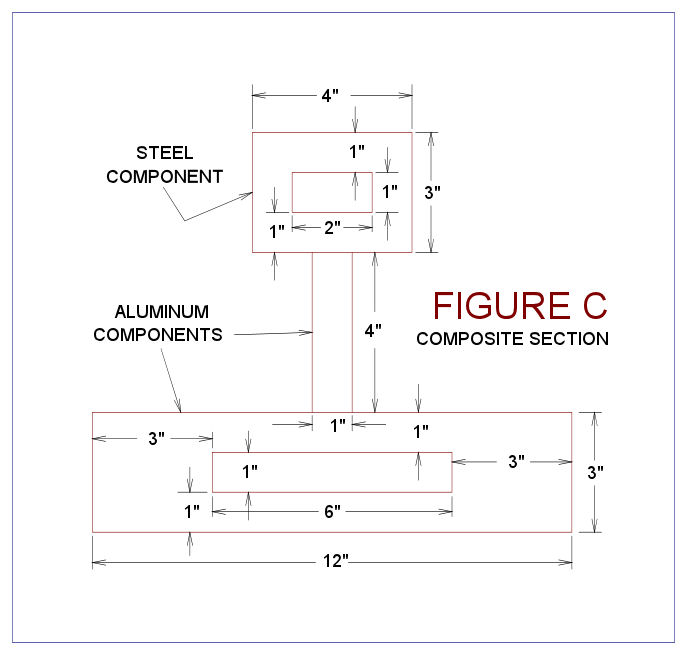
This new cross section is partially composed of elements that are described in Example
1. More specifically the element on top made of steel as in
Example 1; the middle element is a new 1" x 4" aluminum flat bar, which
is standing vertically; and the bottom is aluminum element as shown in
Figure B of Example 1. Figure C requires transformation; this
transformation is shown below. Note that the upper steel element
was transformed as per Example 1.
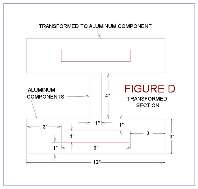
The transformed sections moment of inertia for this new section is calculated as
I = (4"/2 + 1.5")2 x (12" x 3" - 1" x 6") + 2 x 26.5 + (1/12)
x 1" x (4")3 = 3.52 x 30 + 53 + 5.333 = 425.833 in4
The largest stress
in the aluminum will be at the bottom of the member, the section modulus
corresponding to this stress is computed as follows:
SM1 = (I / y) = 425.833 / (4"/2 + 3") = 85.167 in3
Stress1 = M / SM1
The largest stress
in the steel will be at the top of the member, and the section modulus
corresponding to this stress is computed as follows:
SM2 = (I / y) x [1 / (E2/E1)] = [425.833 / (4"/2 + 3")] x (1/3) = 28.389
in3
Stress2 = M / SM2
Since M is the
same, the steel will be under a larger stress because it's section
modulus is smaller. But the steel also has a larger allowable
stress which helps offsets it's greater stress levels.
The preceding
sample section was selected solely for conceptual teaching purposes.
Due to inevitable minor deformities from the construction process, this
section may twist some when it is subjected to flexural loads.
Without additional checks, it is not recommended that a section looking
like this actually be used in practice. Fortuitously most boat,
ship and barge structural shapes less susceptible to twisting action.
Another Example - Douglas Fir and Fiberglass Laminate
This example cross consists of a 2" x 4" piece of Douglas Fir plywood
that is standing upright on a 1/4" thick 14" fiberglass plating element
that is laying flat. The fiberglass is standard laminate as per ABS
requirements. This example is presented on
Composite
Beam Equivalent Area Method Example.
Summary
The cross section properties of a two material beam can be easily determined through the
"Equivalent Area" method. This method transforms one
material's cross sectional area to facilitate the other material that is
present. After transformations are made the whole cross section
can be evaluated in a conventional manner, that is as one homogenous
material.
The transformation is accomplished by multiplying area sections by a "transformation
factor." The transformation is always lateral and not vertical.
The transformation factor is the modulus of elasticity of the material
being transformed divided by the modulus of elasticity of the base
material of the cross section. Portions of the beam that are made
out of the base material are not transformed.
The transformed
section is evaluated just like a isotropic material section. With
the exception, that an original material moments of inertia, if they are
used, are also multiplied by transformation factor. This refers to
the moments of inertia about the neutral axis of original material.
This may occur if the original material's area properties are pulled off
a table (AISC table for example) or computed by hand (like for a
triangular shape). This would not apply, if the original material
was a rectangle, and it's moment of inertia about it's own neutral axis
is calculated based on the transformed area of the element involved.
Section modulus
values of base material elements require no modifications. But
section modulus values of non-base material must be divided by the
transformation factor to give a section modulus that applies to the
non-base material. Alternatively, the non-base material stress can
be calculated as if it is base material, and then modified by
multiplying the base material stress by the transformation factor, which
will yield the stress present in the non-base material.
Primary References
Composite beam
analysis is described described on the web in several places. Some
of these places are listed as follows:
-
EN358 Ship Structures, Course Notes, U. S. Naval Academy,
Annapolis, MD. This is a large document, see the section
entitled "Composite Beam Approach (Dissimilar Materials)."
-
High Strength Composites Course, University of Utah. The
section entitled "Composite (laminated) beam" applies in this
discussion.
-
Mechanics eBook: Composite Beams, University of Oklahoma.
See last section entitled "Alternative Method - Equivalent Area."
-
Rules for Building and Classing Reinforced Plastic Vessels,
1978, American Bureau of Shipping.
-
NVIC 8-87, Notes on Design, Construction, Inspection and Repair of
Fiber Reinforced Plastic (FRP) Vessels, USCG, Washington, D. C..
This is a very large document, for pertinent details go to Enclosure
1, Part B Determining Section Modulus and Moment of Inertia.
-
Buckling of Transversely Framed Panels, Chapter 3, Marine
Composites, Eric Greene Associates, Annapolis, MD. See pages
172 and 173 for an example of composite section calculations.
-
Rules for Materials and Welding, Part 2 Aluminum & Fiber
Reinforced Plastic (FRP) (Chapters 5-6), 2006 American Bureau of
Shipping.
-
Fiberglass Boat Design and Construction,
by Robert J. Scott, 1996 Second Edition, Society of Naval Architects
& Marine Engineers.
-
Fiberglass Boatbuilding for Amateurs,
by Ken Hankinson, 1982, Glen-L Marine Designs, Bellflower,
California.
Applications: The concepts described in this article are utilized in the following templates:
Though not directly related to composite analysis,
learning the parallel axis theorem is helpful for structural analysis. This subject is
covered in an article that is entitled
"Parallel Axis Theorem."
|